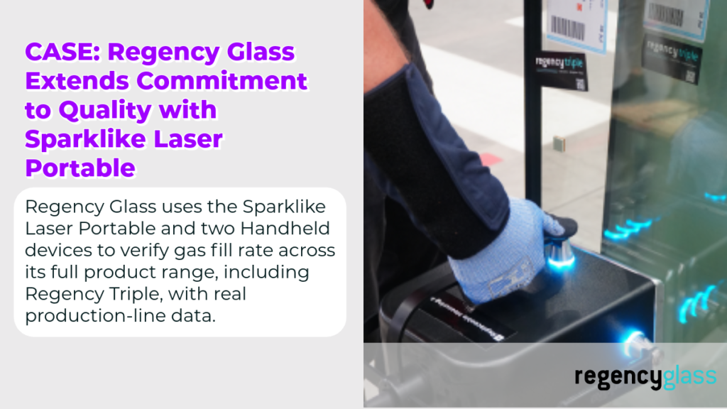
Sparklike Laser™ devices measure the gas fill rate of insulating glass units through the glass, without breaking the unit or adding any components inside it. This article explains how the measurement technology works, how it was developed, and how coatings and laminated glass affect the measurement.
The article is based on an interview with Kai Niiranen, R&D Engineer at Sparklike since 2010, who developed the analysis technology behind the Sparklike Laser™ product line. Niiranen holds a master’s degree in Optical Technology and a bachelor’s degree in Automation and Electronics. Before joining Sparklike, he worked as a Production Engineer at Nexstim, a manufacturer of brain navigation and stimulation systems, and as a Testing Engineer at Planmed, a mammography equipment manufacturer. Both are Finnish high-technology companies with global operations.
Development of Sparklike Laser™ Devices
Why a new technology was needed
Niiranen developed the Sparklike Laser™ product line in response to changes in the insulating glass industry. A growing number of insulating glass units were being manufactured with coatings on both sides, as well as with laminated glass. Manufacturers needed a new technology that could measure the gas fill rate non-invasively through coated and laminated glass.
How the technology was chosen
The development process moved through four phases:
- Mapping: a wide range of non-destructive measurement techniques used in gas detection were identified and compared.
- Screening: techniques that could not measure through glass, whether clear, coated or laminated, were ruled out.
- Comparison: the remaining options were evaluated by achievable accuracy, price, size and power requirements.
- Selection: the final choice was laser-based TDLAS technology.
From laboratory device to production line
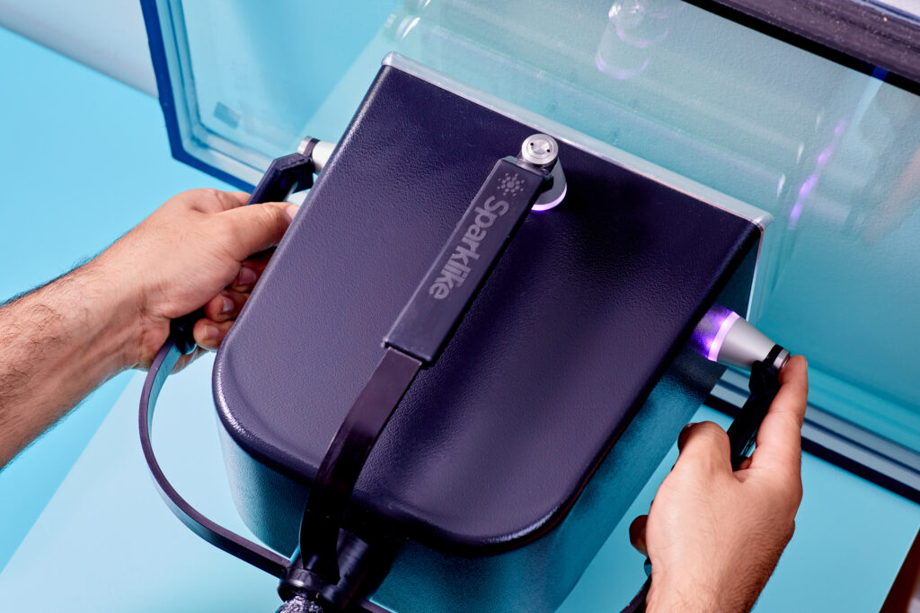
The first device in the product line was Sparklike Laser Standard™, an offline solution for test laboratories and desktop use. The same technology was later built into a robust case with wheels and a battery for use in factories and on building sites, creating Sparklike Laser Portable™ in 2016. In 2018, Sparklike introduced Sparklike Laser Integrated™ (originally Sparklike Laser Online™), a custom-built solution integrated into the IG production line for automated inspection. Sparklike also manufactures Sparklike Laser Components™, which provides the TDLAS measurement technology as components, while the customer builds the mechanical movement and line integration.
Read also: Why break the insulating glass unit for gas analysis if you don’t have to?
How TDLAS Technology Measures Gas Fill Rate
All devices in the Sparklike Laser™ product line are based on TDLAS (Tunable Diode Laser Absorption Spectroscopy). The device uses a narrow-linewidth diode laser at a wavelength of 760 nm, in the near-infrared range, which is specific to oxygen. The laser’s wavelength is modulated across an oxygen absorption line, and the strength of the resulting signal is proportional to the amount of oxygen in the cavity.
From oxygen to gas fill rate
Strictly speaking, a Sparklike Laser™ device is a non-invasive oxygen meter. It measures the residual oxygen in the cavity and converts the result into the insulating gas concentration. Air contains about 20.9 % oxygen, so the measured oxygen shows how much air remains in the unit, and the rest is insulating gas:
Gas fill rate = 100 % − (measured oxygen % ÷ 20.9 %) × 100 %
For example, if the device measures 2.09 % oxygen, the cavity contains 10 % air and the gas fill rate is 90 %.
How the laser beam travels through the unit
- Double glazed units: the beam passes through the first pane, crosses the cavity and is reflected back to the detector from the first surface of the second pane.
- Triple glazed units: the device first measures the combined value of both cavities, then the first cavity. Based on these two results, it calculates the gas fill rate of the second cavity.
Before the measurement, the device scans the unit by moving the focused laser beam through the glass and collecting the reflected signal. This determines the thickness of the panes and cavities, which the calculation depends on: an error in the thickness measurement leads directly to an incorrect gas concentration. For laminated and toughened glass, which can affect the thickness measurement, the devices offer preset values.
Measurement time and accuracy
A measurement with Sparklike Laser Portable™ takes 20 to 30 seconds. The accuracy of Sparklike Laser Portable 2.2 has been validated by ift Rosenheim, and later versions are based on the same TDLAS technology.
Download the ift Rosenheim Report.
How Coatings and Glass Layers Affect the Measurement
Sparklike Laser™ devices can measure most commercial insulating glass units, including double and triple glazing, laminated glass and the majority of coatings. What determines the measurement quality is how much laser light returns to the detector.
Why visible light transmission doesn’t predict measurability
Glass and coating transmission is usually specified for visible light, at 400 to 700 nm. Sparklike Laser™ devices operate at 760 nm, in the near-infrared range, where coatings can behave very differently. Two coatings with similar visible transmission can let through very different amounts of light at 760 nm.
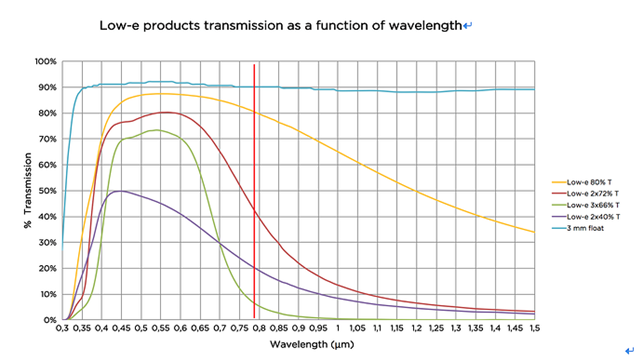
As a rule, measuring through a pane with transmission below 35 % at 760 nm is not recommended.
Why the coating position matters
When light hits a glass surface, part of it passes through, part is reflected and part is absorbed. Together, these always add up to 100 %:
Reflection + Transmission + Absorption = 100 %
The measurement needs both: enough light passing through the first pane, and enough light reflected back from the surface behind the cavity. The surfaces of a unit are numbered from the outside in, starting with surface 1.
- A low-transmission coating on the pane the beam enters weakens the signal, since the light passes through it on the way in and on the way back.
- A reflective coating on the surface behind the cavity strengthens the signal. Aggressive solar control coatings, which are difficult to measure through, can therefore be beneficial when the device measures against them from the other side.
- Clear glass only is not ideal either, since clear glass reflects little light and most of the signal is lost. Measurements remain reliable, particularly when looking at average values.
The Sparklike Laser user guide illustrates this with a triple glazed unit with a low-e coating on the middle pane. Of 100 units of light sent into the unit, 33 return from the first cavity when the coating is on surface 3. When the same coating is on surface 4, only 6 units return. In a unit with three clear panes, 11 units return.
In practice, if a unit has a low-transmission coating on one side, the problem can usually be solved by measuring from the other side.
Check your glass structure
To see whether a specific glass structure can be measured, use the Sparklike Laser Compatibility Checker. For practical tips on choosing the measuring side, preparing the device and getting repeatable results, read the Essential Guide to Sparklike Laser Measurement.
Want to know which Sparklike Laser™ device fits your production? Contact Sparklike or your nearest distributor.
Updated in October 2026